Industrial CT scanning matters because it lets manufacturers see and measure the inside of a part without cutting it open. Using X-rays captured from hundreds or thousands of angles, a computed tomography system builds a full 3D model of both external and internal geometry, revealing porosity, cracks, voids, assembly errors and hidden dimensions that no caliper, probe or optical scanner can reach. That makes it one of the most powerful non-destructive testing tools available for quality control, failure analysis, reverse engineering and faster product development.
In short, its importance comes down to three things: it finds defects that other methods miss, it measures features that cannot be reached any other way, and it does both without destroying the part. The sections below explain how the process works, where it is used, how it compares with other inspection methods, its limits, and how to get useful results from a scanning provider.
From Hospital Scanner to Factory Floor
Computed tomography was developed for medical imaging and became common in hospitals from the 1970s onward. Over roughly the last two decades, falling hardware costs, better detectors and faster reconstruction software have pushed the technology firmly into manufacturing. Today it is used in labs and, increasingly, inline on production lines to check castings, plastic moldings, electronics, batteries, medical devices and sealed packaging.
The principle is the same as a medical scan, but industrial systems are tuned differently. Because a machined part does not move or breathe and is not harmed by radiation dose, the scanner can use higher energies and longer exposures to reach much finer resolution. For a deeper look at the science behind CT imaging and reconstruction, you can enter here to read a published scientific overview.
How Industrial CT Scanning Works, Step by Step
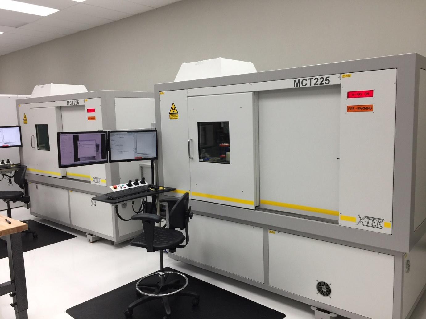
- Fixturing: the part is mounted on a precision turntable between an X-ray source and a flat-panel detector, inside a shielded cabinet.
- Projection capture: the turntable rotates in small steps while the detector records a 2D X-ray image at each angle. Denser or thicker material absorbs more X-rays and appears darker.
- Reconstruction: software combines the projections into a 3D volume made of voxels, each holding a gray value related to material density.
- Surface determination: the software finds the boundary between material and air, turning the volume into a measurable surface or point cloud.
- Analysis: engineers run nominal-to-actual comparisons against CAD, wall thickness checks, porosity and inclusion analysis, or export the data for reverse engineering.
Resolution depends mainly on part size: the smaller the object, the closer it can sit to the source and the finer the detail. Small components can often be resolved down to a few microns, while large castings are scanned at coarser voxel sizes. Very dense materials such as steel need higher-energy sources, and large, dense parts may require specialized high-energy systems.

Key Industrial CT Scanning Applications
Non-Destructive Testing and Defect Detection
CT reveals internal porosity in aluminum die castings, shrinkage cavities, cracks, inclusions of foreign material and trapped powder in additively manufactured parts. Each defect can be located, sized and color-coded in 3D, so engineers can decide whether a part is acceptable against their specification rather than guessing from a sectioned sample.
Dimensional Metrology
Metrology-grade CT systems measure internal and external features in a single scan: bores, channels, undercuts and wall thicknesses that a coordinate measuring machine (CMM) probe could never touch. Results are usually shown as a color deviation map comparing the scanned part with its CAD model. Many labs follow the VDI/VDE 2630 guideline series for CT dimensional measurement and state measurement uncertainty alongside results.
Reverse Engineering
When you have a physical part but no drawings or CAD data, for example a legacy component or a supplier part, CT captures the complete geometry, including internal passages, so it can be rebuilt as a mesh or parametric CAD model. That shortens the path to reproduction, redesign or replacement.
Assembly Verification and Failure Analysis
Because assemblies can be scanned intact, CT shows whether clips are seated, seals are compressed, springs are in position and connectors are fully mated. In failure analysis, it lets investigators see the failed part as it was before any teardown disturbs the evidence.
Packaging and Seal Integrity
In pharmaceuticals and personal care, inline or at-line CT can check container closures, blister packs and seals on pill bottles for air-tightness and correct fill, without opening the package.
Additive Manufacturing
3D-printed metal and polymer parts often have internal lattices, conformal cooling channels and enclosed cavities that cannot be inspected from the outside. CT is one of the few ways to confirm that unfused powder has been removed, that channels are open along their full length and that porosity stays within limits. It is widely used to qualify new print parameters before a part goes into series production.
Electronics and Batteries
In electronics, CT shows solder joint voids, wire bond positions and hidden connector defects on populated boards. In battery cells, it can reveal electrode alignment, overhang, foreign particles and swelling, all without opening a cell, which matters because teardown of a charged cell is hazardous and destroys the evidence.
Industrial CT vs. Other Inspection Methods
| Method | Sees internal features? | Contact with part | Typical strengths | Limitations |
|---|---|---|---|---|
| Industrial CT | Yes | None | Complete 3D data, internal defects, complex geometry | Higher cost, slower scans, size and density limits |
| Tactile CMM | No | Probe touches part | Very high accuracy on accessible features | Point-by-point, cannot reach hidden features |
| Optical or laser 3D scanning | No | None | Fast surface capture, large objects | Struggles with shiny surfaces, no internal data |
| 2D radiography | Partly | None | Quick, lower cost defect screening | No depth information, features overlap |
| Destructive sectioning | Yes, one plane | Part is cut | Direct view of microstructure | Destroys the part, sees only one slice |
Contact measurement collects individual points relative to each other, using CMMs or articulating arms for small or localized features, while non-contact methods such as laser trackers, photogrammetry and structured light scanners capture larger surfaces quickly. CT complements both by capturing what they cannot see.
When Is CT Worth the Cost?
| Situation | CT is a strong fit | A simpler method may do |
|---|---|---|
| Internal channels, cavities or lattices | Yes | Rarely |
| First-article inspection of a complex casting or molding | Yes | CMM if all features are external |
| Simple external dimensions on a few features | Usually not | CMM, gauges or optical scanning |
| Root-cause analysis of a sealed assembly | Yes | Sectioning if the part can be sacrificed |
| Very large, dense steel parts | Only with high-energy systems | Ultrasonic testing or 2D radiography |
Business Benefits of Industrial CT Scanning
- Better product quality: hidden defects are found during development and first-article inspection, before parts reach customers.
- Shorter development cycles: one scan can replace dozens of sectioned samples and multiple measurement setups, which speeds up design iterations and tooling corrections.
- Lower inspection costs: parts stay intact, so expensive prototypes and assemblies are not destroyed for analysis.
- Stronger supplier management: incoming parts can be checked objectively against CAD, with clear visual reports to share.
- Traceable evidence: the 3D dataset can be archived and revisited if questions come up later.
Industries using CT include aerospace, automotive, defense, energy, electronics, medical devices and battery manufacturing, as well as research labs studying materials and advanced components. It fits naturally alongside other developments in industrial technology, such as those covered in our look at new catalyst technology and solutions.
Limitations to Plan For
- Artifacts: beam hardening and streaks near dense metal can distort data, especially in mixed-material parts.
- Size and density: large or very dense parts may need high-energy systems or may not be scannable at useful resolution.
- Time and data: high-resolution scans can take from minutes to hours and generate very large files.
- Cost and expertise: systems are a major capital purchase and need trained operators, which is why many companies use outside scanning services instead.
- Radiation safety: X-ray cabinets are regulated in the United States, with federal performance standards and state radiation control programs covering registration and safe operation.
How to Get the Most From a CT Scan
A scan is only as useful as the question it is meant to answer. Before sending parts out, it pays to prepare properly:
- Define the goal. Porosity screening, full dimensional inspection and reverse engineering each need different settings and resolution. Say which one you need.
- Share the CAD model and drawing. Nominal data and tolerances let the lab align the scan and report deviations that matter to you.
- Identify critical features. Point out the bores, walls or regions of interest so the lab can focus resolution where it counts, sometimes with a separate zoomed scan.
- Mention the materials. Multi-material assemblies with metal inserts in plastic may need special settings or filtering to limit artifacts.
- Agree on acceptance criteria. Decide in advance what pore size or deviation counts as a reject, so the report leads directly to a decision.
Scanning a small sample of parts first, rather than a whole batch, is a sensible way to confirm that the settings and deliverables fit your needs before committing to a larger program.
Choosing an Industrial CT Scanning Service
Unless you scan parts every day, outsourcing is usually the practical route. When comparing providers of industrial CT scanning, ask about:
- The maximum part size, weight and material density their systems handle.
- Achievable voxel size for your specific part, not just the machine’s best-case figure.
- Whether they provide metrology with stated measurement uncertainty or only visual inspection.
- Deliverables: reports, deviation maps, STL files, CAD reconstruction and raw volume data.
- Turnaround times, confidentiality agreements and pricing structure, which is often per scan, per hour or per project.
If you work with electrical components, our guide to the types of current transformers is another practical engineering read.
Frequently Asked Questions
What is industrial CT scanning?
It is a non-destructive X-ray technique that builds a complete 3D model of a part, including its internal structure, from many 2D images taken as the part rotates on a turntable.
Why is industrial CT scanning important?
It finds internal defects and measures hidden features without cutting the part open. That improves quality control, speeds up development and avoids destroying expensive prototypes or failed parts.
How is industrial CT different from medical CT?
The principle is the same, but industrial systems rotate the part rather than the scanner and can use higher energies and longer exposures. That gives much finer resolution on inanimate objects.
What defects can industrial CT find?
Common findings include porosity, voids, cracks, inclusions, wall thickness problems, trapped powder in 3D-printed parts, misassembled components and poor seals.
Can CT scanning replace a CMM?
Not always. CT measures hidden features a CMM cannot reach, but a tactile CMM can still offer very high accuracy on accessible features, so many manufacturers use both.
Which industries use industrial CT scanning?
Aerospace, automotive, defense, energy, electronics, medical devices, packaging, additive manufacturing and battery production all use it for quality control and failure analysis.
Bottom Line on Industrial CT Scanning
Use industrial CT when the answer you need is inside the part: hidden porosity, internal channels, assembly fit or the cause of a failure. Start with a clear question, share CAD data and acceptance criteria, and pilot a few parts with a provider before scaling up, so the scans lead straight to a pass, fail or design decision.